Overview
The cooling system was my first system-level project. The previous design was rushed into production and had room for improvement. I was given the responsibility of improving the design and preparing for the design review at competition.
keeping it cool
The cooling system was my first system-level project. The previous design was rushed into production and had room for improvement. I was given the responsibility of improving the design and preparing for the design review at competition.
After reviewing the old design, it was clear that the weight could be improved upon. Rubber hoses were used for all the routing and adapters between these hoses were large and heavy, sometimes requiring multiple reducers to convert sizes. By viewing data logs, I observed that the cooling system never reached a steady operating temperature and would rise until the driver stopped. This could cause the car to overheat during the endurance event
My design process started with using data logs to quantify the cooling need. An equation for heat loss was given from the motor controller manufacturer, and an efficiency map was given by the motor manufacturer. Using these, I wrote a Python extension to our data log program that would calculate the waste heat for each timestep and find the average heat output, 3.56kW.
Using this number, I researched heat transfer calculation methods, and came across a research paper with heat dissapation numbers for given radiator sizes. Looking at the sensitivity of these numbers showed that making the radiator tubes longer or thicker was not as efficient as adding tubes, so a thin, short radiator was chosen. The final dimensions were 12"x7" after normalizing ambient and operating temperatures to our use case.
I consulted our Aerodynamics lead, who helped me analyse CFD simulations to determine placement and explained incompressible flow to lead me to the air diffuser design.
By carefully reviewing datasheets, I found that the motor required a pressure higher than most common water pumps deliver, so a special pump was specified and the motor and motor controller cooling was moved from a series to a parallel setup. This change was validated on the bench by measuring the water pumped through the system over a given time.
To prove that the system was meeting specification, a data aquisition board was designed to sense the temperature difference across the core and flow rate, giving the amount of heat disappated.
The system weight was reduced to 70% of the last year, with only 600g of weight in the radiator. Data logs show that the temperatures stay under the maximums set by the manufacturers, even for an endurance event on a hot day. The system has been reused on the 2018 and 2019 cars because the speed margin of redesigning the system is small for the amount of effort it would take to overhaul the system.
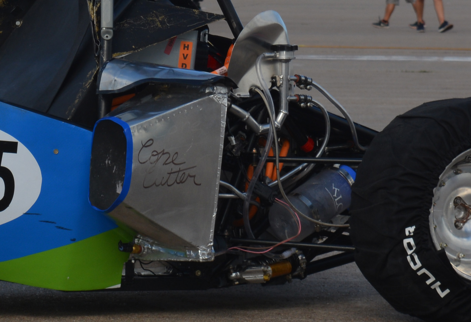
To make a radiator that fit our exact dimensions, we could have paid for a custom radiator to be made, but I saved money by using the waterjet and welder we had available. Using Solidworks, I modelled the end tanks for our specified dimensions, including holes for sensor mounts. These were waterjet out of sheet aluminum. I had welded the steel frame before, but I practiced welding aluminum before I tried making the end tanks. I knew what had to be done to make the right design, so I took it upon myself to pick up the skills.
To quantify our weight savings, every piece of each system was weighed. The weight of the previous system was 4.24kg and the new system was 2.95kg, making it 70% of the previous system's weight. 1kg of the savings came from moving from rubber hoses to aluminum tubing and 400g coming from the custom built radiator. The system was much lighter, even when adding an aluminum shroud for improved airflow and including the larger pump required.
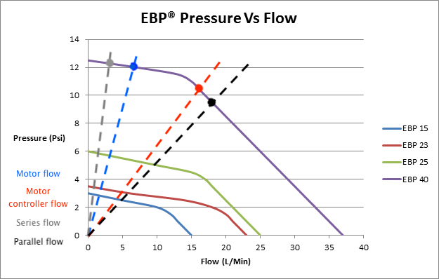
The motor and motor controller both specifiy a coolant flow rate to maintain cooling under high load, and the previous design's pump did not account for the motor's abnormally high pressure requirements. Using a technique from electronics design, the operating point can be found using the pump's supplied pressure-flow graph. The flow requirement of the motor was 6L/min and the motor controller needed 8L/min. The datasheets show the required pressure, 13psi for 7L/min and 5psi for 8L/min irespectively. As you can see in the graph, the operating points move from around 2L/min in the series configuration on a smaller pump to nearly 10x more by going to the parallel setup and EBP40.
The PCB developed for the cooling system fit lots of features onto a <1 sq.in board. The pump power was controlled using an onboard MOSFET, two coolant temperature sensors and a flow seonsor were read, a pump-unplugged safety light to warn when the pump was disabled manually, and all information was communicated to the control system over CAN bus. This was accomplished by using an 8 pin, 8 bit microcontroller and making the design as lean as possible.
All the firmware was written in C, which involved writing libraries from scratch to communicate to the CAN tranceiver and ADC. I had to use datasheets to find the timing information, formatting, and configuration for these chips. The system was debugged using oscilloscopes and digital logic analysers until it worked.
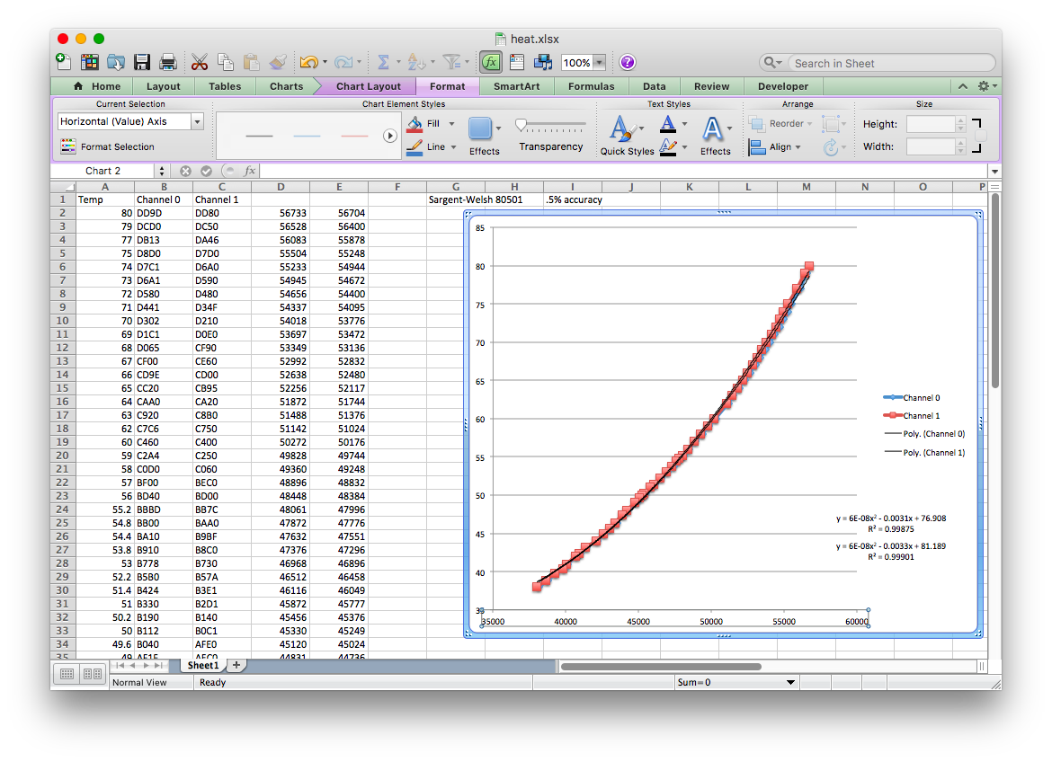
To accurately measure the coolant temperature, I created calibration curves by heating water and measuring the temperature with both sensors and a precision mercury thermometer. I created a curve fit with a high R value that the control system would use as a transfer function.